Instruction scheduling is essential to modern compilers. It tries to hide latencies and increases the throughput of a straight line code by reordering the enclosing instructions. In order to do that, compilers have to know a whole bunch of information, ranging from individual instruction’s latency to microarchitecture details. The system that describes these is called a scheduling model. In LLVM, a scheduling model is used by not just the instruction scheduler, but also target-specific optimizations like MachineCombiner and components like MCA (Machine Code Analyzer)1. Which makes it an important factor in performance tuning for low-level code.
This series is about LLVM’s scheduling model, how it interacts / affects other parts of LLVM and how can we fine tune this model for better performance. I’ll cover how scheduling models are used in other part of LLVM in later posts, but in this one, I’m focusing on the scheduling model itself first, and talk about how to specify scheduling information for individual instructions. Let’s start with a really basic example.
The Basics
Scheduling models are part of the target definition. They are associated with one or more target processors. Multiple processors can also share the same scheduling model. Take RISC-V as an example, we can find one of its scheduling models, SiFive7Model, covers a wide array of processors from sifive-e76, a 32-bit microcontroller, to sifive-x280, which is a high-performance processor designed for AI/ML workloads.
To describe per-instruction scheduling information like latency, naively, we can express such information with descriptions like “opcode ADD has latency of X”. It’s all fun and games until you realize that there are tens of thousands of opcodes in some of the targets2 so it doesn’t scale well. More importantly, many instructions share the same scheduling characteristics. For example, simple arithmetic operations like add, sub, and shifts usually have the same latency in most modern architectures.
Instead of spelling out per-opcode information, LLVM chooses a different path that characterizes an instruction’s scheduling properties with operand reads and writes: First, each operand in an instruction is assigned with a “token”.
Take the DIV instruction in RISC-V shown below as an example, WriteIDIV is the token assigned to the first operand, which is also the destination register, hence a write operand (also called definition). The two ReadIDIV follow are tokens for the two source registers, both are read operands (or use).
1// From llvm/lib/Target/RISCV/RISCVInstrInfoM.td.
2def DIV     : ALU_rr<0b0000001, 0b100, "div">,
3              Sched<[WriteIDiv, ReadIDiv, ReadIDiv]>;
A write token is a SchedWrite TableGen instance, while a read token is a SchedRead instance.
With these SchedWrite and SchedRead tokens, a scheduling model then assigns processor-specific information to them, like latency and the hardware resources they use.
Take SiFive7Model we saw earlier as an example, in the file where the model is defined (i.e. llvm/lib/Target/RISCV/RISCVSchedSiFive7.td), we find this piece of snippet:
1// Integer division
2def : WriteRes<WriteIDiv, [SiFive7PipeB, SiFive7IDiv]> {
3  let Latency = 66;
4  let ReleaseAtCycles = [1, 65];
5}
The WriteRes TableGen class3 takes a SchedWrite – in this case WriteIDIV – and assigns it three different kinds of information:
- Latency of 66 cycles
- The hardware resources it uses:
SiFive7PipeBandSiFive7IDiv - The
ReleaseAtCyclesfield specifies the number of cycles this instruction spends on each hardware resource it uses. In this case,WriteIDIVspends 1 cycle onSiFive7PipeBand 65 cycles onSiFive7IDiv
What about ReadIDIV, the SchedRead instances we saw earlier? By default, LLVM’s scheduling model assumes that operand reads finish instantly, so a SchedRead cannot be assigned a latency property nor consuming any cycle the same way as a SchedWrite.
Which means that effectively, write operands dictate the instruction’s scheduling properties and it’s expected to represent majority of the changes an instruction makes to the processor states. So, it’s safe to say that in this case, an DIV instruction has a latency of 66 cycles.
Alright, so far we have covered the most basic part of a scheduling model, specifically on how to specify the scheduling information for an instruction. We can summarize it into three quick steps:
- Assigning
SchedReadandSchedWriteto your instruction - In your scheduling model, find the processor resources
SchedWriteuse… - …and map those resources to
SchedWriteusingWriteRes, along with other info like latency.
I have intentionally left many details aside, like what exactly is a hardware resource (e.g SiFive7PipeB). These details are strongly related to what we’re going to cover in the next section: the microarchitecture of a processor.
Modeling microarchitecture
Recall the goals of instruction scheduling are to minimize latency, maximize throughput, and eliminate as many potential hazards in the processor’s pipeline as possible. These goals have a lot to do with how instructions move within the processor’s pipeline. For instance, extra cycles might be spent on fulfilling RAW (Read after Write) data dependencies, or certain units, like an integer division unit, might be overwhelmed and stall the entire pipeline.
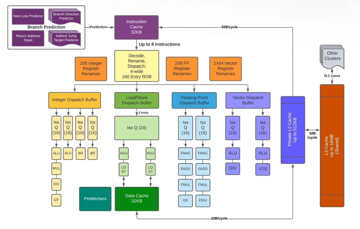
And this is where the processor’s microarchitecture comes into play. Specifically, we’re focusing on superscalar architecture here, which has a typical structure shown below:

The above structure has an issue width of 3, meaning it can feed at most 3 instructions to later stages at a time; micro-codes, or uops, are generated at the decode stage; at this moment we’re a little hand-waving on the definition of dispatch and issue, as we’ll see several of their variants later; there are three different functional units in the execution stage for integer, floating point, and memory instructions (load / store unit). All of them are fully pipelined.
Despite the fact that scheduling model has strong connections with microarchitectures, we don’t want our model to cover too many microarchitecture details – it’s simply too expensive! What we want is a model that can raise red flags when we come up with a bad scheduling, yet abstract away all the nitty-gritty details and present just the information we care.
“What kind of red flags?” you may ask. The most important thing is probably whether we have enough resources to even run an instruction. Remember, the whole idea of superscalar is to run instructions of different types in different function units in parallel: integer uops go into integer units and floating point uops go into another floating point unit, where these units can run independently. Each of these units has one or more pipes that actually run the uops. In many places “functional units” and “pipes” are interchangable. If there is no enough resource, we won’t be able to dispatch an uop into any of the pipes. After all, processors have only a limited number of pipes for a specific type of instructions.
Let’s look at a concrete example: SiFive’s P670 RISC-V processor.
P670 is an out-of-order processor targeting consumer devices like smartphones. It has four integer pipes, two floating point pipes, and two vector units. And this is how integer pipes look like in its scheduling model:
1def SiFiveP600IEXQ0       : ProcResource<1>;
2def SiFiveP600IEXQ1       : ProcResource<1>;
3def SiFiveP600IEXQ2       : ProcResource<1>;
4def SiFiveP600IEXQ3       : ProcResource<1>;
5...
6def SiFiveP600IntArith    : ProcResGroup<[SiFiveP600IEXQ0, SiFiveP600IEXQ1, SiFiveP600IEXQ2, SiFiveP600IEXQ3]>;
In LLVM, a ProcResource instance in TableGen represents a unit that can executes uops, hence an equivalent to a single pipe in most cases. Here, each integer pipe in P600 is represented by SiFiveP600IEXQ[0-3]
Nevertheless, it’s not the only instance you can dispatch uops to, because sometimes you can dispatch uops into a collection of pipes in which any of the pipes in that group can execute the dispatched uop. Such groups are represented by ProcResGroup instances in TableGen, like the SiFiveP600IntArith we see above: when an instruction – like ADD who uses WriteIALU – consumes a SiFiveP600IntArith shown in the snippet below, it means that such instruction can be dispatched to any of the SiFiveP600IEXQ[0-3].
1// Integer arithmetic and logic
2def : WriteRes<WriteIALU, [SiFiveP600IntArith]>;
When there is no available pipe, a stall or a hazard occurs, in this case it is considered a dispatch hazard since you can’t dispatch more instructions. To avoid such hazards, each pipe usually has a buffer or a queue to store a certain number of candidates. Knowing the size of that buffer is crucial to our scheduling model, because then we can make a wiser decision on distributing the instructions evenly across all pipes, rather than jamming them into a single one just like freeways in LA.
Most4 processors with buffers / queues like this have a more well-known functionality: reordering instructions. In an our-of-order processor, each of these buffers is used as some sort of staging area for the scheduler to preemptively issue instructions with no dependencies on the others, in the hope of hiding latencies.
Aside from the size of the buffer, how to organize these buffers (e.g. several pipes might share a buffer) is just as important as their sizes. In the next section, we’re gonna go through processor resource buffers of different sizes and layouts.
Processor resource buffers
Let’s sort out some terminologies first. The buffer, or scheduler queue we’re talking about here, is often known as a reservation station too. Reservation station stores instructions whose operands might not be ready yet, until those operands are available. Reorder buffer (ROB), on the other hand, is a kind of unit with slightly confusing name. ROB reorders the results of an instruction; it’s usually depicted at the end of the execution stage, as shown in the previous diagram. Nevertheless, we need to reserve a slot in the ROB before we can even dispatch an instruction, therefore, to some extent, the size of ROB also controls how many instructions are allowed into the execution stage.
Back to the buffers, in LLVM’s scheduling model, we use the BufferSize field in a ProcessorResource or a ProcResGroup instance to specify the size of the associated buffer.
Special values are also used to denote unconventional buffer layouts, or even the absent of buffers.
LLVM currently supports 4 different kinds of buffer layouts: decoupled reservation stations, unified reservation station, in-order core, and latency device. Let’s go through each of them now.
Decoupled reservation stations

When we assign a positive BufferSize to individual processor resources or processor resource groups, we’re modeling processor resources with their own scheduler queues. Here is an example from PowerPC POWER9’s scheduling model:
1// Only one Branch unit.
2def BR : ProcResource<1> {
3  let BufferSize = 16;
4}
Here, the execution unit for branch instructions has its own scheduler and it has 16 entries in its buffer.
A more common arrangement is assigning BufferSize on a processor resource group.
For instance, in AMD Zen2 CPU, there are total of 4 general integer execution units with their own schedulers; each scheduler has 16 buffer entries.

In Zen2’s LLVM scheduling model, these schedulers are represented by 4 ProcessorResource instances: Zn2ALU[0-3].
Despite the fact that there are 4 separate schedulers in real hardware, Zen2’ scheduling model doesn’t assign BufferSize = 16 to each Zn2ALU[0-3] instance, but instead group all 4 instances into a single ProcResGroup called Zn2ALU and assign a buffer size of 16 * 4:
1// 64 Entry (16x4 entries) Int Scheduler
2def Zn2ALU : ProcResGroup<[Zn2ALU0, Zn2ALU1, Zn2ALU2, Zn2ALU3]> {
3  let BufferSize=64;
4}
The rationale behind this is that most integer instructions map Zn2ALU, rather than a specific Zn2ALU[0-3], to their SchedWrite token. Because similar to the SiFive P600 example we’ve seen earlier, these instructions simply don’t care which Zn2ALU[0-3] they are going to run on. Therefore, it makes more sense to specify the buffer size on the processor resource group.
Unified reservation station
By default, BufferSize is set to -1, representing a layout where all the processor resources effectively share the same buffer as illustrated in the diagram below.

In this case, the actual size of such buffer is dictated by MicroOpBufferSize, which is a global attribute to the entire scheduling model rather than individual processor resource:
1def SiFiveP600Model : SchedMachineModel {
2  let IssueWidth = 4;         // 4 micro-ops are dispatched per cycle.
3  let MicroOpBufferSize = 160; // Max micro-ops that can be buffered.
4  ...
5}
This MicroOpBufferSize attribute is primarily used to throttle the number of uops to be dispatched. There are, however, many factors that control this throttle at the same time. Notably, ROB and register renaming. We’ve explained the effect of ROB earlier; for register renaming, if there aren’t enough physical registers for us to rename, a dispatch hazard also occurs. Consequently, the value of MicroOpBufferSize should be the minimal of reorder buffer size, size of register renaming pool, and the actual size of unified reservation station.
In-order core
So far we have been discussing out-of-order cores, which is one of the primary reasons why we need buffers in the first place. But in-order cores are still a thing, because it dramatically simplifies the chip design and reduces the area, which are top on the list for products like embedded devices. It’s also getting more popular in cases where you want save areas for specialized units like BIG vector units or even matrix multiplication units. SiFive’s X280, which we’ve seen its scheduling model previously, and X390 are good examples, where they save area by adopting in-order design and enjoying a whopping 512- and 1024-bit vector, respectively.
For in-order cores, you simply set BufferSize and MicroOpBufferSize mentioned earlier to zero.
When an uop is handed to an in-order unit in LLVM’s scheduling model, dispatch and issue are considered happening at the same time.

The uop then holds the processor resource until ReleaseAtCycle before another uop can be dispatched. In other words, the younger uop would encounter a dispatch hazard until ReleaseAtCycle has passed in the older uop.
Latency device
When BufferSize equals to 1, we create a unique kind of resource known as latency device. Resources of this kind act just like an in-order pipeline, except two things:
- Since there is still a buffer, albeit being a really small one, a younger uop waits in the buffer until the older uop finishes, rather than encounters a dispatch hazard.
- LLVM’s instruction scheduler always treats two adjacent uops that use this resource as producer and consumer (even if there is no data dependency between them). Meaning, the younger uop always waits
Latencycycles after the old uop was issued – as opposed to waiting untilReleaseAtCyclehas passed in a normal in-order pipeline – before it can be issued.
This kind of resource was designed to model in-order units within an out-of-order core. It’s most commonly used for modeling un-pipelined units nowadays (which, of course, is in-order). Yes, it’s 2024 and there are still computations that are difficult to be pipelined, most notably integer – sometimes even floating point – divisions. It is possible to make integer divisions pipelined, but many of the times it’s not worth the chip area.

Some examples: Samsung Exynos M5’s serialized (i.e. un-pipelined) integer division unit, represented by M5UnitD from here, has a buffer size of 1:
1let Super =  M5UnitC, BufferSize = 1 in
2def M5UnitD  : ProcResource<1>; // Integer division (inside C0, serialized)
RISC-V’s Rocket chip marks their integer and floating point division units, RocketUnitIDiv and RocketUnitFPDivSqrt, as latency devices too:
1let BufferSize = 1 in {
2def RocketUnitIDiv       : ProcResource<1>; // Int Division
3def RocketUnitFPDivSqrt  : ProcResource<1>; // FP Divide/Sqrt
4}
Epilogue
In this post, I went through the basics of LLVM’s scheduling model and show how to specify the scheduling information for individual instructions. On top of that, I explained different kinds of processor resource buffers and their use cases.
In the next post, I will talk about how exactly these resource buffer kinds and latency are used in LLVM’s instruction scheduler and LLVM MCA, as well as their performance impact on the generated code. Which helps us to make a better decision on designing new scheduling models.
It should have been used in more places like instruction selection and cost models in the middle end, but that’s a story for another day. ↩︎
Interestingly, RISC-V has one of the biggest sets of opcodes. A large portion of them are pseudo instructions for RVV. ↩︎
Using
WriteResis not the only way to connectSchedWritewith processor resources. I might talk about an alternative that involvesInstRWandSchedWriteResin future posts. ↩︎Superscalar and out-of-order-ness are two independent concepts. Superscalar is about increasing the “width” of your execution units; out-of-order is about the order of executions. You can have in-order superscalar processors, which are pretty common, as well as out-of-order non-superscalar processors, which barely exist but no one can stop you from making it. ↩︎